In this edition
- COVID-19
- Passive fire protection measures
- What is a fire control plan in regards to the AMSA575 Form?
- Using CE documentation for Class 1, 2 and 3 vessels
- Equivalent solutions
- Guidance for renewal survey—internal hull inspection and internal foam buoyancy.
COVID-19
We find ourselves in a new world since the last Survey Matters, with many of us working from home and subject to restrictions on movements.
AMSA continues to provide services during this period and has put in place contingency plans to mitigate disruptions to statutory activities.
We acknowledge that it may be difficult to arrange surveys, audits, inspections and service equipment during this period, particularly if travel is required. If you find yourself in these circumstances as a result of COVID-19 restrictions, please contact us directly at dcvsurvey@amsa.gov.au to discuss the circumstances.
At this point in time, following the directions of the Australian Government, we understand that surveys may still occur, whilst still observing social distancing rules in place. However AMSA will consider cases on a case by case basis if a community or vessel cannot be surveyed or facilities are not available.
Find more information about what we are doing to support the industry.
Passive fire protection measures
A fire on a ship is dangerous to human life. The recent loss of 34 lives on Conception in California is evidence of this.
Most people are familiar with active fire protection measures like alarms, fixed fire-extinguishing systems, portable fire extinguishers, and fire blankets.
However, passive structural fire protection can actually contain or slow the spread of fire at its point of origin. These measures provide time for a master and crew to assess and act in a controlled manner. This includes abandoning ship in a worst case scenario before loss of life occurs.
Did you know?
Modern fire standards for risk assessment only put the chance of active systems working at around 90%
For example:
Literature from the 4th international conference on performance based codes and fire safety standards indicates that sprinkler systems and fire alarm systems are both considered to have a reliability of 90%
When developing NSCV C4, the National Maritime Safety Committee (NMSC) considered a 10 year period of fires on-board vessels in Australia. In that period there were 66 (reported) fires on-board. Fourteen of those fires resulted in a total loss of the vessel (21%). Analysis of the fire source data shows that machinery is by far the major source of fires on-board. This is machinery mostly in the engine room (twice the occurrence of the next most common source - electrical fires). Nine of the recorded incidents occurred in machinery spaces that contained a fixed fire extinguisher. Six of those nine incidents still led to total loss of the vessel or major consequences (67%).
Structural fire protection:
Structural fire protection is installed on the vessel structure to contain or slow the spread of fire. It includes the installation of fire-resistant bulkheads, deck heads, decks and doors.
The primary aims of structural fire protection are:
- Prevent or delay the spread of fire, smoke and heat within high risk spaces.
- Protect essential systems and spaces to enable evacuation from the immediate area. This also ensures persons on board can reach muster stations and then abandon ship, should the fire become unmanageable.
- Provide redundancy and work alongside active fire protection systems. This avoids vulnerability arising from over-reliance on a single measure.
Passive structural fire protection works in four main ways:
1. Protects structural elements
Structural fire protection guards essential components and compartments against fire and thermal heat, to maintain structural integrity.
2. Compartmentation
Compartmentation includes fire-rated divisions or compartments, bulkheads, deck heads, and smoke barriers. It seeks to contain the spread of fire, thermal mass and smoke. Fire can be contained within the machinery space, for example, if the bulkheads and decks are sufficiently protected.
3. Opening protection
Fire doors and fire-resistant penetrations installed in openings aim to maintain fire-resistance. They work together to form an effective smoke and fire barrier.
4. Fire stopping materials
These materials generally withstand temperatures exceeding 1200oC for extended time periods. This limits fire spread.
Note: It’s common to see a fire-rated division penetrated during modifications. Workers may leave hidden holes in the division as they perform maintenance and upgrades. Surveyors need to pay attention to fire-rated divisions. Ensure they are maintained to the original approved specification. Pay particular attention to cable and pipe penetrations.
The type and thickness of insulation depends on the material it is protecting. For example; steel begins to lose its design margin of safety at temperatures of around 550oC. For aluminium the temperature is much lower at around 150oC. At 275oC aluminium will lose around 50% of its yield strength. Composites soften as temperatures rise, resulting in reduced structural properties for a laminate. The glass transition temperature of the resin affects the amount of insulation required for a composite. Performance of cores & fibres across a range of temperatures also impacts the amount required.
Examples of structural fire protection
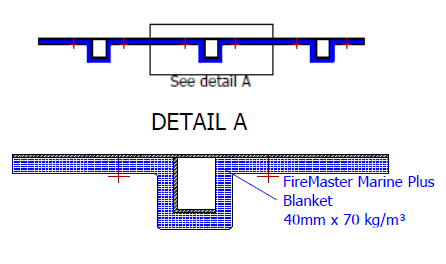
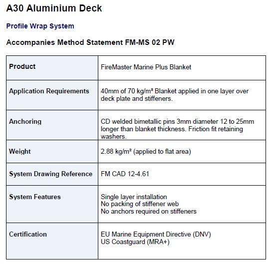
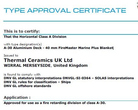
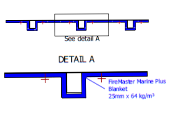
Aluminium – A30
Basic principles
Example data sheet
Example certificate of compliance
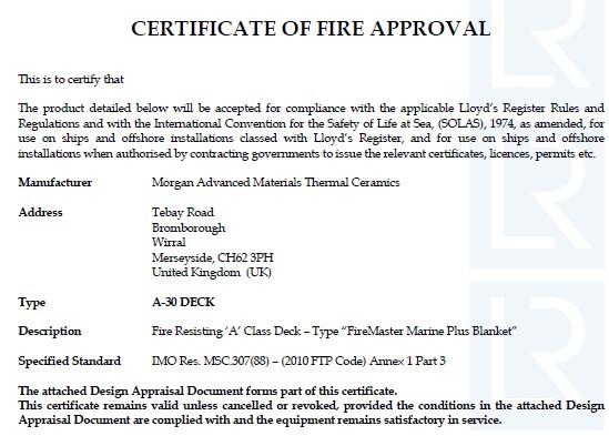
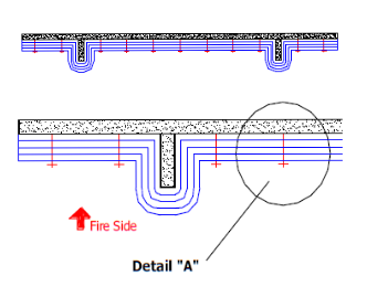
Steel – A30
Basic principles
Example steel data sheet
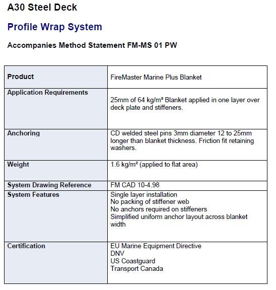
Example certificate of compliance
Composite – A60
Basic principles
Example data sheet
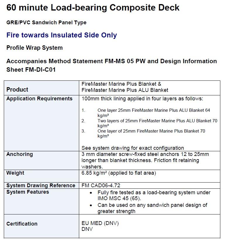
Example certificate of compliance
Key items a surveyor should verify
Installing protection under approved design and OEM guidelines is the only way to achieve the aims mentioned above. This includes:
- Ensuring only appropriately tested solutions are used.
- The requirements of the performance standards (Fire Test Procedures Code or the High Speed Craft Code) are specific. Products not designed and tested to meet these standards are not acceptable (see below).
- Insulation requirements vary based on type and thickness of the material it is protecting. Requirements also vary depending on the area on the vessel and the time rating of the division.
- Having concise and accurate approved drawings, of the proposed arrangements.
- Verifying that materials and fittings are correctly installed by competent personnel, i.e. as stated in the approval documentation and/or the manufacturer’s instructions. For example, pins are fixed to the substrate correctly. Pins are sufficient in nature as per approval documentation and achieve required returns.
- Verifying that the means of protection are inspected and tested at regular intervals. This includes prompt repair and renewal whenever necessary.
- Checking the certification of the SFP, do not confuse non-combustible products, with those properly tested and certified as part of time rated fire-resisting divisions (structural fire protection).
Examples of unacceptable products
Pink batts are not acceptable. They are combustible above 350oC and are designed for comfort insulation and acoustic use only.
Intumescent paints and similar solutions do not meet the performance requirements for use. They are not approved for use as structural fire protection solutions.
A solution approved for use on steel, is not necessarily suitable for use on aluminium or fibreglass. Even if it is certified for a higher time rating than required.
A solution approved for use in a land based building is not approved for use on a vessel. The performance criteria are significantly different between vessels and buildings. The environment, firefighter response time and distance to safety or rescue if a fire breaks out differ.
Interested in learning more about fire protection or looking for approved products?
- Overview of aluminium alloy mechanical properties during and after fires
- A master’s guide to Fire Safety on Ferries
- MarED – Marine Equipment Directive approval register
- DNV GL Approval finder
- Lloyds register approval finder
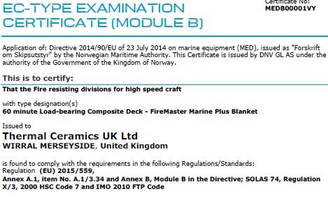
- Morgan thermal ceramics – firemaster certificates
What is a Fire Control Plan in regards to the AMSA575 Form?
Let’s have a look at Fire Safety, specifically the AMSA575 form.
This form requires a surveyor to survey the ‘Fire Safety Preparedness documentation’:
Fire safety preparedness documentation
| Item | Survey checks | Tick/Cross/N/A | Surveyor comments/ drawing/ document reference |
|---|---|---|---|
| Fire control plan | Examination and confirmation of fire control plan. Visual inspection to ensure vessel is built and equipment arranged as per plan. | ||
| Fire training manual | All elements of Clause 6.3 of NSCV C4 provided to allow vessel owner/operator to develop training manual. | ||
| Fire safety operational booklet | Information in accordance with Clause 6.3 of NSCV C4 provided to allow operator to develop their fire safety operation booklet to meet 6.4 requirements. |
Chapter 6 of NSCV C4 requires vessels specified in table 29 to have a fire control plan, a fire training manual and a fire safety operational booklet.

This documentation provides vital information for an operator to comply with Marine Orders 503 and 504, (including for the carriage of dangerous goods if applicable). A vessel may also need to carry information about fire safety to comply with Workplace Health and Safety and other legislation.
When you conduct a fire safety survey and you look at the Fire Control Plan, ensure you reference NSCV C4, 6.2.
The fire control plan is a very useful document in the case of an emergency and for crew training purposes. It allows for quick identification and location of firefighting apparatus and safety equipment on board. The plan also identifies escape routes and safest pathways to fight fires. It provides detail on compartments, decks, bulkheads, ventilation systems and remote operating systems.
ISO 17631 compliant fire control plans must show the following for each deck, as applicable:
a) Control stations;
b) Sections of the craft enclosed by fire–resisting divisions;
c) Smoke zones;
d) Evacuation alarms;
e) Fixed fire detection and fire alarm systems;
f) Fire appliances;
g) Personal protective equipment including fire-fighters outfits and emergency escape breathing devices;
h) The means of access to various compartments and decks in the vessel;
i) The ventilating system (including location of fan controls, smoke flaps, and fire dampers);
j) The location of international shore connection if fitted; and
k) The position of all means to control the fuel shut-off valves, ventilation shutdowns, fixed fire detection and fire alarm, and fixed fire-extinguishing systems.
The vessel must have a fire control plan permanently exhibited in a location suitable for ready reference by the crew. Generally this is a clearly visible location close to accommodation, engine rooms and the wheelhouse.
Vessels >35m measured length require a duplicate set of fire control plans or a booklet containing such plans. This must be stored in a prominently marked weather tight enclosure outside the deckhouse to assist shore-side firefighting personnel.
A surveyor must ensure the plan is a true representation of all firefighting locations and safety equipment on-board. There must not be any discrepancies.
You may also need to review maintenance and service records to conduct this survey.
So as we can now see, providing a tick and a few comments for a fire control plan on the AMSA575 is not that simple. The more complex the vessel, the more complex the survey may be.
Using CE documentation for Class 1, 2 and 3 vessels
For class 1, 2 and 3 vessels, the NSCV limits the use of CE documentation for initial survey. It can only cover the design and construction phases of the hull, superstructure and appendages for these vessels. This approach is only available for vessels able to use the ISO12215 structural standards under NSCV C3. This allows the use of ISO standards as deemed to satisfy solutions for vessels that are:
- Less than or equal to 13m in measured length; and
- used in light operations such as recreational activities.
All other areas of the vessel must undergo initial survey against the applicable NSCV standards. Initial survey includes the design, construction and commissioning phases.
Design phase:
Plan approval must include documentation outlining all requirements of the standards applicable to the vessel. This documentation must contain:
- Approved plans; and
- Checklists for use by the construction surveyor to ensure each part of the applicable standard is addressed
Where certain requirements of a standard can't be met, apply for an equivalent means of compliance or specific exemption.
Typical areas of CE vessels to consider under the design phase may include but are not limited to:
NSCV C1:
- Guardrails and bulwarks / Special purpose decks
- Stairs, stepladders, seating, access and reboarding, berths and deck areas
- Escape and evacuation route
- Navigation light configuration
- Vision from the helm
- Glazing in the operating compartment
NSCV C4:
- Remote closing of ventilation and fuel systems
- Fire resistant divisions
- Galley design
- Materials and fitout
- Fire detection, alarm and extinguishing
- Means of escape
NSCV C5A:
- Propulsion system including shaft, couplings, stern glands and brackets.
- Bilge systems
- Fuel system including fuel tank construction
NSCV C5B:
- Electrical schematics for vessels with 240VAC
NSCV C5C:
- LPG schematic of installation
NSCV C6B:
- Quantity and positioning of buoyancy foam / watertight compartments / air chambers
- Location of watertight bulkheads, collision bulkheads, watertight doors
- Air chamber number and sizing in collared vessels.
NSCV C7A:
- Stowage and launching of safety equipment
USL Code 5D / 5E:
- Heights and locations of air pipes and ventilator
- Window, hatch and side scuttle design and location
- Freeing ports, coamings and scuppers
- Sea inlets and skin fittings
Construction phase:
The construction phase for already built CE vessels is distinct from that of a new build. Under SAGM 3.9.3 the construction phase surveys of hull, superstructure and appendages are deemed to be satisfied if:
- Appropriate CE documentation is provided
- The surveyor verifies the condition of the structure is acceptable. Note: This involves inspecting the vessel out of the water.
Requirements for areas other than structure:
- Verify that the vessel is in accordance with the documentation supplied in the design phase.
- Verify the condition of all items is acceptable.
- Inspect electrical installations against the approved schematics (where applicable).
- Submit AMSA563 and/or AMSA564 for the initial survey of the electrical system.
Commissioning phase:
Commissioning phase surveys are as required for any other vessel. Note that stability is not covered by the CE certification. It must be assessed against the NSCV C6 requirements. Provide an approved stability book accompanied with approval letter and stability notice.
See Survey Matters December 2019 for more information on stability documentation requirements.
Vessels with 240V AC power require a state electrical certificate of compliance.
For more information see DCV-ITS-016 Imported CE leisure craft.
Equivalent solutions
"One ship drives east and another drives west.
With the selfsame winds that blow.
'Tis the set of the sails,
and not the gales,
that tell us the way to go."
Ella Wheeler Wilcox, The Winds of Fate, 1916
East or west?
Like charting a course, design choices have risks and consequences. East may lead to safety, west to peril, so how do we decide which way to go?
Seafarers can follow trade routes, use charts to avoid shallows, and rely on the accumulated and documented knowledge of their peers. Designers can do the same, using standardisation.
The National Standard for Commercial Vessels (NSCV) provides a safe course for designers and builders to follow. In the language of the NSCV, that safe course is known as the deemed to satisfy solution. This is a tried and well-trodden path, like following a trade route to a destination.
For more intrepid adventurers however, the NSCV recognises that departing from the trodden path is a requirement for innovation. To this end, the NSCV allows stakeholders to develop their own path. NSCV calls this equivalent solutions.
The NSCV enables equivalent solutions by providing overarching requirements known as required outcomes. This type of writing in a standard is generally known as “outcome or performance based”. Think of required outcomes like safety “destinations”, they are there so we know where to aim.
However, despite knowing where to aim, many adventurers embark down a path without regard, or consideration, of the risks. They fail to consider the hazards and pitfalls that can arise along the way or they also make no attempt to address potential hazards with controls.
It is not just enough to set off for the highest mountain peak, the intrepid adventurer needs to consider the risks and make sure they are equipped for the journey.
In vessel design we can compare the risks of a proposed solution against the deemed to satisfy solution provided in the NSCV. This is a simple way to consider the risks in context and examine the effectiveness of any new proposed controls, against known acceptable solutions.
By doing this a designer can:
- compare the residual risks and performance of a proposed solution against the deemed to satisfy solution; and
- demonstrate the proposed solution is at least as effective as the item it replaces.
By achieving an equivalent safety outcome to solutions already accepted, you demonstrate that a solution not only heads out in the right direction, but also has the same or better chance of reaching the destination.
Thinking of making an application for an equivalent solution?
- Read the specified solutions outlined in the NSCV; and
- Ensure your proposed solutions provide the same level of safety as the specified solutions
The last thing anyone wants is an equivalent solution that is unsafe, costly and time consuming.
Guidance for renewal survey—internal hull inspection and internal foam buoyancy.
The practicality of inspecting internal buoyancy or sealed internal hull voids is a long standing issue. SAGM recognises this and provides some relief. It limits the inspection at a renewal survey to a ‘reasonable extent’.
This approach is captured by the additional items listed for a vessel’s ‘second renewal survey’:
(d) verify internal foam buoyancy if not fully inspected during the five yearly in and out of water survey because of inaccessibility;
(e) internal hull inspection if not fully inspected during the five yearly in and out of water survey because of inaccessibility;
In general, the ‘second renewal survey’ will not occur before July 2023. That is, at the expiry of the second certificate of survey issued by AMSA. E.g. if the first CoS issued by AMSA in July 2018, had a renewal survey date of December 2018 then the 2nd renewal (ie 10 year survey) would occur in December 2023.
Table 9 of SAGM sets out the scope and depth of a renewal survey. We expect a surveyor to conduct an internal inspection to a level that allows them to recommend issue of a new CoS. This may require removal of sample sections of foam or use of a borescope. If you use a sampling approach, provide reports for both the foam inspection and internal hull inspection. Submit them alongside your survey reports and ensure they contain locations, extent and results. This will allow an AMSA delegate to make an informed decision.
Planning the extent and location of an internal inspection on a foam filled vessel
- Ensure you can conduct a representative inspection of the condition of frames, stiffeners and brackets. This includes corrosion, cracked frames or welds, tripped or deformed brackets, and evidence of fatigue.
- Consider any findings from the external inspection when conducting an internal inspection.
- Talk to the owner about the requirement to inspect more fully at the 10 year survey so they can plan for the event.
We recognise ambiguity still exists. Surveyors are individuals with personal thresholds for what is acceptable or robust. As such we intend to provide more guidance and clarification around survey practices like these in the future.