What’s changed
This marine notice supersedes 2024/03. It:
- clarifies AMSA’s expectations for testing and operating oil filtering equipment
- adds detail on sample line flow and alarm response times
- explains how port State control officers assess system performance and compliance
- highlights where non-compliance(s) with MEPC.107(49) and the ISM Code will result in deficiencies
- clarifies requirements for managing and sealing sample line valves
- reinforces that the alarm and stopping device must trigger during clean-water flushing.
Guidance for
Vessels required to meet MARPOL Annex I Regulation 14, including:
- ship operators
- masters
- engineer officers
- recognised organisations
- flag states.
Purpose
AMSA continues to identify defective oily water separators, or systems being operated in a non-compliant manner, during port State control inspections. In some cases, crew are not familiar with correct operating procedures.
Resolution MEPC.107(49) sets the international approval standard for oil filtering equipment under MARPOL Annex I Regulation 14. It is given effect in Australian law by Marine Order 91 (Marine pollution prevention — oil) 2025.
This marine notice provides guidance on the installation, testing and correct operation of oil filtering equipment (oily water separators) to support compliance with these requirements.
Installation requirements
Oil filtering equipment installed on or after 1 January 2005 must be approved to meet Resolution MEPC.107(49) and comply with MARPOL Annex I Regulation 14.
The equipment must:
- supply a truly representative effluent sample with adequate pressure and flow to the 15ppm bilge alarm (6.2.2).
- include fail-safe arrangements to prevent any discharge in the event of malfunction (4.1.3).
- be fitted with a 15ppm bilge alarm that:
- includes an electronic device pre set to activate when effluent exceeds 15 ppm or if the bilge alarm fails (4.2.7)
- meets the required response time – no more than 5 seconds between a change in the sample and the correct ppm display reading (4.2.6)
- be arranged to minimise the response time when discharge exceeds 15 ppm, including activation of the automatic stopping device. The total response time must not exceed 20 seconds (6.2.1).
Typical MEPC.107(49) installation
The diagram shows the configuration of a 15ppm bilge separator system with an oil content monitor (OCM), bilge alarm, sample line, automatic stopping device, and recirculating facilities.
It illustrates how bilge water flows through the separator, with representative sampling to the OCM and includes fail-safe arrangements to prevent overboard discharge when oil content exceeds 15 ppm.
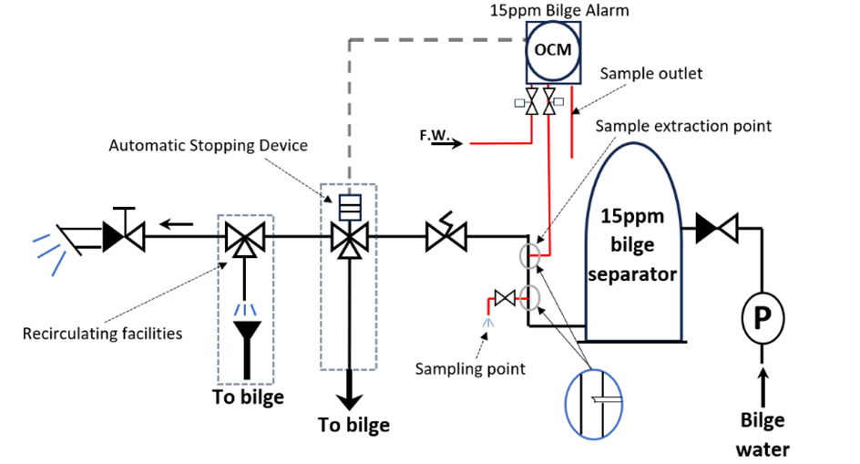
Figure 1- Diagram of a typical MEPC.107(49) installation
Inspection and testing during port State control
AMSA port State control officers (PSCOs) may inspect the condition and operation of equipment as described in the Procedures for Port State Control, 2023 Resolution A.1185(33).
This includes the:
- oily- water separator
- filtering equipment and alarm
- stopping or monitoring arrangements.
Representative effluent sample
PSCOs verify the effluent supplied from the oily water separator to the 15ppm bilge alarm is a truly representative sample.
During operational testing, the equipment must be:
- configured to circulate from bilge tank to bilge tank (recirculating facility)
- supplying an effluent sample to the 15ppm bilge alarm OCM
- simulating discharge of bilge separator effluent overboard.
During the simulation, the PSCOs confirm whether the sample is representative, with adequate pressure and flow, as required by MEPC.107(49) 6.2.2.
This is verified by visually observing the sample flow at the OCM outlet.
Recognised organisations may recommend sealing valves or union joints on the sample piping to ensure the valves are locked and sealed in their normal operating position. This prevents wilful manipulation in accordance with MEPC.107(49) 4.2.10.1.
Alarm and stopping device
PSCOs may verify the flow overboard stops if the oil content exceeds 15 ppm.
When a sample greater than 15ppm is applied:
- the alarm must activate
- the automatic stopping device (3-way valve) must stop discharge overboard.
Under MEPC.107(49) 4.2.10.2, opening the valve (manually or electrically) to supply clean water to the OCM for cleaning or calibration must also activate the 15ppm bilge alarm and automatic stopping device.
Response time performance
PSCOs may observe whether response times meet the required limits:
- no more than 5 seconds for the ppm display to show a change of oil content
- no more than 20 seconds for the automatic stopping device to activate when oil content exceeds 15ppm.
Fail-safe operation
PSCOs may verify that the system is installed in a fail-safe manner to avoid overboard discharge in case of a malfunction of the 15ppm alarm system, including disruption of the effluent sample flow.
Sample line valve assessment
The sample line is a critical part of the 15ppm bilge alarm system.
The sample flow through the OCM of the 15ppm bilge alarm should be unobstructed during PSC inspections and during regular operation.
Where valves are fitted to the sample lines, AMSA PSCOs may assess their configuration and operation to confirm the system cannot be bypassed or manipulated.
PSCOs may consider the below scenarios.
Valves positioned for correct operation
If operational testing begins with sample line valves open and supplying a representative flow through the OCM, this indicates the system is being used correctly in service.
Unsealed shut off valves
If a shut off valve on the 15ppm bilge alarm sample line can be operated without breaking a seal, the system may be considered non-compliant with MEPC107(49) 4.2.10.1.
However, if closing the valve automatically stops overboard discharge (for example by activating the 15ppm bilge alarm and the automatic stopping device), the purpose of MEPC107(49) 4.2.10 will be met, as the arrangement prevents wilful manipulation.
Clean water flushing
If the 15ppm bilge alarm does not activate when the valve supplying clean water for cleaning or calibration is open, the system is non-compliant with MEPC 107(49) 4.2.10.2.
In this situation, wilful manipulation is possible because the OCM can be supplied with a non-representative sample.
No or inadequate sample flow
If operational testing begins with no, or clearly inadequate, sample flow through the OCM and the system continues to discharge overboard, the system is non-compliant with MEPC107(49) 6.2.2.
Further investigation will determine whether the cause is:
- a blockage in any part of the sample line. This indicates non-compliance with the maintenance and shipboard operation requirements of the ISM code.
- a closed valve on the sample line. This indicates non-compliance with the shipboard operation requirements of the ISM code and also non-compliance with MEPC 107(49) 4.2.10.1 as the OCM can be bypassed.
Inspection photos and compliance indicators
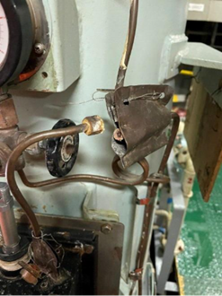 Figure 2 - a blocked 15ppm bilge alarm sample line outlet with no flow. | 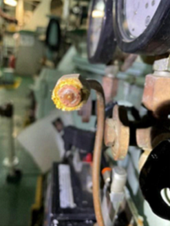 Figure 3 – another view of a blocked 15ppm bilge alarm sample line outlet with no flow. |
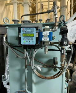 Figure 4 - a flow sensor and alarm fitted to the 15ppm bilge alarm sample line. | 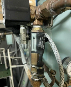 Figure 5 – a detailed view of a flow sensor and alarm fitted to the 15ppm bilge alarm sample line. |
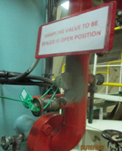 Figure 6 – sample line valve to 15ppm bilge alarm open with signage fitted. | 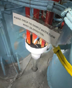 Figure 7 – a verification of flow of sample water from sealed open with signage fitted. |
Non-compliance and deficiencies
If operational testing does not achieve expected outcomes, PSCOs may carry out a more detailed inspection to assess whether blockages, wilful manipulation or incorrect operation are contributing factors.
Where non-compliance is identified, the ship may be issued a deficiency and/or detained until the equipment meets all requirements and crew can demonstrate adequate familiarity with operating the system.
Non-compliance with the requirements relating to unsealed shut-off valves, clean water flushing or inadequate sample flow may result in pollution. Temporary measures (such as sealing sample line valves in their correct operating position to ensure the sample flow cannot be stopped or manipulated), may be accepted if approved by the issuer of the International Oil Pollution Prevention (IOPP) Certificate.
If non-compliance results in detention, AMSA may require the IOPP Certificate issuer to verify the arrangement has been brought into compliance.